
The 4AD has a Hypoid bevel drive rear end with semi floating shafts. Two types of units were used. The Salisbury 6HA had an integral final drive housing, axle tubes and detachable rear cover and the Moss unit had a detachable final drive assembly and rear cover welded to a banjo casing.
To remove the axle from the car, jack in front of the rear springs, disconnect the propeller shaft, brake linkage and shock absorbers. Remove both wheels and check straps, then lift the axle assembly through the frame sideways.
Moss axle — The half-shafts (interchangeable) are carried on ball bearings retained against the shoulder at the outer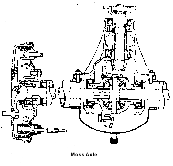 end by a nut and locknut with a tab washer between them. The outer race of the bearing is carried in a housing spigoted and bolted to the axle tube flange with the brake back plate. There is a lipped oil seal in the bearing housing, lip to bearing. The outer end of the half-shaft is upset to form a flange for the wheel studs and brake drum. The half shaft passes through the lipped oil seal (lip inwards) inside the axle.
The bevel pinion shaft is carried in taper roller bearings pressed into the final drive housing from front and rear. Distance-piece between inner races with shims for bearing adjustment. Shims behind the outer race of rear bearing for pinion mesh adjustment.
The crown wheel is spigoted and bolted to the flange of the one piece differential cage by eight set screws. Hardy Spicer needle roller bearing universal. The side bevel gears run directly in the cage with flat joints, series 1110. There are nipples for lubrication of thrust washers behind. The planet bevel pinions joints have spherical thrust washers and run on the spindle retained by a split pin.
The differential assembly is carried in taper roller bearings in split housings with shims behind the outer races for bearing and mesh adjustment.
The bearings should be adjusted by shims before the bevel pinion is installed until there is no play and no drag. After installation of the bevel pinion, shims should be changed from one side to the other to give .006 – .008 in backlash.
Salisbury axle — The hubs are keyed on tapered half-shafts (interchangeable). Taper roller bearings in axle tube ends are retained by back plates with shims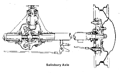 behind (.003, .005, .010, .030 in thick) to adjust end float (.006 – .008 in). The inner ends of the half-shafts butt on a floating thrust block around the planet bevel spindle.
To remove the half-shaft, draw off the hub, detach the brake back plate assembly with lipped oil seal in housing and shims. Draw out shaft and bearing carefully through inner oil seal (lip inwards).
The bevel pinion shaft is carried in taper roller bearings. The outer races are pressed into the final drive housing from the front and rear. Shims (.003 ,005, .010, .030 in thick) are used between the shoulder on the shaft and inner race of the front bearing for bearing adjustment. Shims (003, .005, .010 in thick) are used between the outer race of the rear bearing and housing for mesh adjustment.
The pinion setting marked on the face of the pinion (bottom figure of four sets of figures) may be zero, plus or minus. This indicates amount in thousands above or below nominal distance (2.000 in) of face from centreline of the crown wheel. Use mesh adjusting shims to obtain the setting marked and assemble pinion in bearing with the original bearing shims, but without the oil thrower or oil seal. Tighten the driving flange nut and test for preload 18—1 2lb/in).
The crown wheel is spigoted and bolted to the flange of the one-piece differential cage. Side bevel gears run directly in the cage with flat thrust washers behind. Planet bevel pinions have spherical thrust washers and run on the spindle retained by a pin peened to lock. Axle shaft thrust block round spindle.
The differential assembly is carried on taper roller bearings in split housings with shims (.003, .005, .010, .030 in thick) between the inner races and the cage for bearing and mesh adjustment. Install the differential assembly without shims and with bevel pinion removed and mount a dial gauge on the axle casing with button against back face of crown wheel. Move differential assembly to one side of the housing with lever and set gauge to zero. Lever assembly over to the other side and note gauge reading (A). This figure indicates the play in the bearings and the thickness of shims needed to take up play. Add .004 – .006 in to total to give preload. This total must be divided to obtain correct crown wheel mesh as noted below.
After installing the bevel pinion, reassemble the differential, again without shims. Lever it away from the pinion, set the indicator to zero and lever assembly towards pinion. Note reading (B). This, minus thebacklash figure etched on the crown wheel is the thickness of shims to go behind the crown wheel side bearing. The remainder of shims from total (A +.004 -.006in) go behind the offside bearing. When the assembly is complete, check for backlash (.004 in minimum). Change shims from one side to the other of differential bearings if necessary.